| NEW FOREST ELECTRONICS |
|
| PC-based logic analyser model La-Gold-16 |
| Summary |
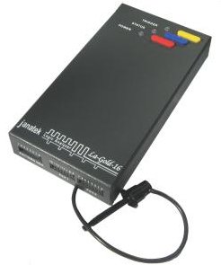
A top-quality 16-channel PC-based
logic analyser with pattern generator, the Janatek La-Gold-16 offers
a comprehensive digital debugging environment for the electronics professional.
It is similar to the La-Gold-36, but with 16 channels instead of 32.
It captures data at a maximum rate of 1GHz and has a buffer depth of up to 1 Meg
samples per channel. It incorporates a pattern generator which can be used to
stimulate the hardware being debugged whilst the logic analyser captures the
response.
| Product |
|
|
|
|
|
LOGIC ANALYSER
|
PATTERN GENERATOR
|
.jpg)
| Benefits |
The
La-Gold-16 is a comprehensive 16 channel high specification logic analyser
designed to speed debugging of digital electronic circuits. The very high
sampling rate provides a more accurate representation of the signals on screen.
(In general the sampling frequency should be 3 to 5 times faster than the
shortest timing change being measured). 1 GHz provides 1 ns between samples.
The huge 1 Meg samples per channel buffer depth (up to 500
MHz sampling rate) allows longer captures without lowering the sampling
frequency, thus maintaining sampling resolution. The combination of these two
features on this analyser is difficult to beat, being especially useful for
capturing high and relatively low frequency signals simultaneously.
Debugging is greatly aided by the integrated 8-bit pattern
generator that can be used at the same time as the analyser is capturing data.
| What's included |
|
| Order code: La-Gold-16 | We regret that we can no longer supply this item |
| Analyser Comparison |
|
|
| Model | Channels | Sampling rate | Max. Buffer depth | Price | Find |
| Annie-USB | 8 | 500 MHz | 1 Meg samples/channel | £125 | click here >> |
| Logic-16 | 16 | 200 MHz | " | Obsolete | click here >> |
| La-Gold-16 | 16 | 1 GHz | " | Discontinued | This page |
| La-Gold-36 | 32 | 1 GHz | " | Discontinued | click here >> |
|
|
| Software |
|
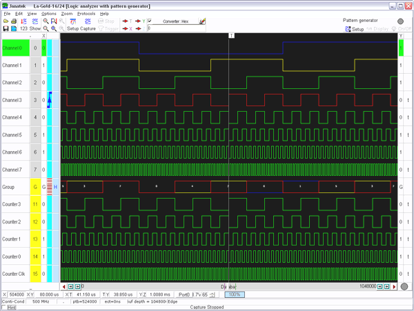
The software for the La-Gold-16 is mature and both the logic analyser and
pattern generator are controlled from a single, intuitive user interface. It
is user friendly, and incorporates feedback suggestions from users. The integrated pattern generator can be used in conjunction with the logic analyser. The user can set up the instrument under test (UUT) with the pattern generator and then measure its response with the logic analyser. This, and other flexible triggering options for both the logic analyser and pattern generator, make the La-Gold-16 a cut above the rest.
|
|||
| The
integrated pattern generator The pattern generator, working in close combination with the logic analyser, adds a new dimension to debugging possibilities.
The outputs of the pattern
generator can act as inputs to the unit under test. The response from the
unit under test can then be used to trigger the logic analyser. |
|
||
.png)
Try the excellent La-Gold demonstration software now! click here to download
| Detailed specification |
(a) Acquisition system (hardware related)
| Number of input channels | 16 digital |
| Input voltage range (max) | -60 to + 60V |
| Impedance | 1 Mohm, 5pF |
| Input bandwidth | 100 MHz |
| Threshold voltage | -5V to +5V (variable for each group of 8 channels) |
| Data buffer |
1 Meg samples per channel for 500MHz and
below sampling 20k samples per channel minimum for 1GHz sampling |
| Pre/post-trigger buffer | The data buffer is divided into pre and post trigger sections. The pre/post buffer relation may be changed in 1000 samples steps |
| Internal sampling clock | Rates - 1GHz
max. to 100Hz min. Stability - 100 ppm |
| External sampling clock |
Synchronised capture: 50MHz max. Synchronised capture into linear/ring buffer Ring buffer configuration: Operates with pre and post trigger buffer Linear capture may start on trigger condition or immediately |
|
Digital
logger clock (Logging to hard disk) |
Log rate - 1 second to 1 hour sampling rate |
|
Post trigger delay (Extended capture time) |
Depends on the sampling rate, at 500 MHZ - maximum delay = 33 ms at 1.25 kHz - maximum delay = 1677 sec |
| Instrument integration | Can combine with pattern generator functionality |
| Hardware self test | Comprehensive hardware self test facilities |
| Extension port | Useful signal inputs/outputs, e.g. output trigger to combine with external oscilloscope, pattern generator strobes, UART Tx/Tx busy, fifo empty/full etc |
| Protocols | UART/RS232 monitor/generate signals (more protocols to be added) |
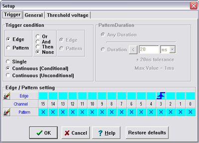
(b) Trigger conditions (configured using software)
| Trigger Methods: Pattern | |
| Pattern valid for any duration | "1", "0" and "don't care" ("X") conditions selectable on all channels |
| Pattern valid < duration | Glitch capture. Pattern duration may be specified in steps of 20ns to 1 ms. Duration tolerance of ±20ns |
| Pattern valid > duration | Pattern duration may be specified in steps of 20ns to 1 ms. Duration tolerance of ±20ns |
| Trigger Methods: Edge | |
| Triggers on: | Rising edge, falling edge, either rising or falling edge (change of state), of any one or combination of channels |
| Mouse/Keyboard | Trigger may be forced |
| Trigger Methods: Combination pattern/edge | |
| Edge OR pattern | Edge or pattern condition that occurs first will cause a trigger |
| Edge AND pattern | For a trigger the edge condition must occur while the pattern condition is valid |
| Edge THEN pattern | The first condition is required before the second condition. At least 30ns is required from detection of the first condition to the second |
| Application of trigger conditions | |
| Single capture | Captures a single set of data |
| Continuous capture display |
Unconditionally continuous - trigger is
forced internally and display updated at
regular intervals. Conditionally continuous - display is updated when a trigger condition is detected. Any of the above trigger conditions may be set as described above. The display is updated on detection of a specified trigger condition |
(c) Pattern generator
|
Pattern source |
Pattern editor or user file |
| Number of channels | 8 |
| Buffer depth | 20KB |
| Data output clock rate | 50 MHz maximum |
| Output signal amplitude | 2.5V to 4.8V |
| Start condition | On logic analyser start or arm, trigger condition, start button |
| Minimum input impedance of load | 4k7 / 100pF |
| Modes of operation | Single/continuous |
(d) S
(d) Software environment
| Operating system | Windows 98, ME, 2000, XP, Vista 32 or later compatible versions |
| PC |
Data capture speed is unaffected by PC speed Ease of use: The software is very easy to use. Most functions are directly selectable by means of function buttons on the main screen |
| Display |
Number of channels - any number of the channels may be displayed Channel/group names - user specified signal names Display order - channel display order user specified Colours - specify colours for individual signals, background Zooming - comprehensive zooming in and out facility Default view is as a timing analyser, i.e. waveforms are shown. When capture has been paused, can be used as state analyser in hex and binary via additional window |
| PC connection |
USB 2.0 High Speed (480 Mbit/sec) USB 1.1 Full Speed (12 Mbit/sec) compatible Standard port type B on hardware unit connects to standard type A on PC using 1.8m USB lead supplied |
| Saving to disk - formats | Binary data, hex, spreadsheet (CSV), configuration |
| Printed output | The timing diagrams, bitmaps, binary and hex data may all be printed in landscape or portrait modes |
(e) Physical and Environmental
| Weight | Hardware unit with test leads - 220 gram (7.8 ounce) |
| Dimensions | Hardware unit only - 162 x 84 x 26 mm (6.4 x 3.3 x 1.0 inches) |
| Environment | The analyser is intended for indoor use |
| Operating temperature | 10 to 40 degrees C (50 to 104 degrees F) |
| Power requirement from USB or external adapter |
2.5 Watt typical (capturing data without
pattern generator) 3.0 Watt typical (including pattern generator) (Power consumption is dependent on the number of channels used and input frequencies) |
| Compliance | CE certified and lead free |
| Manufacturer | Janatek Electronic Designs, South Africa |
| Test leads supplied |
|
|
Illustrated: |
.jpg)
(back)
(click
picture to return)
|
|
(back)
(click
picture to return)
|
|
.jpg)
(back)